
Optical Module
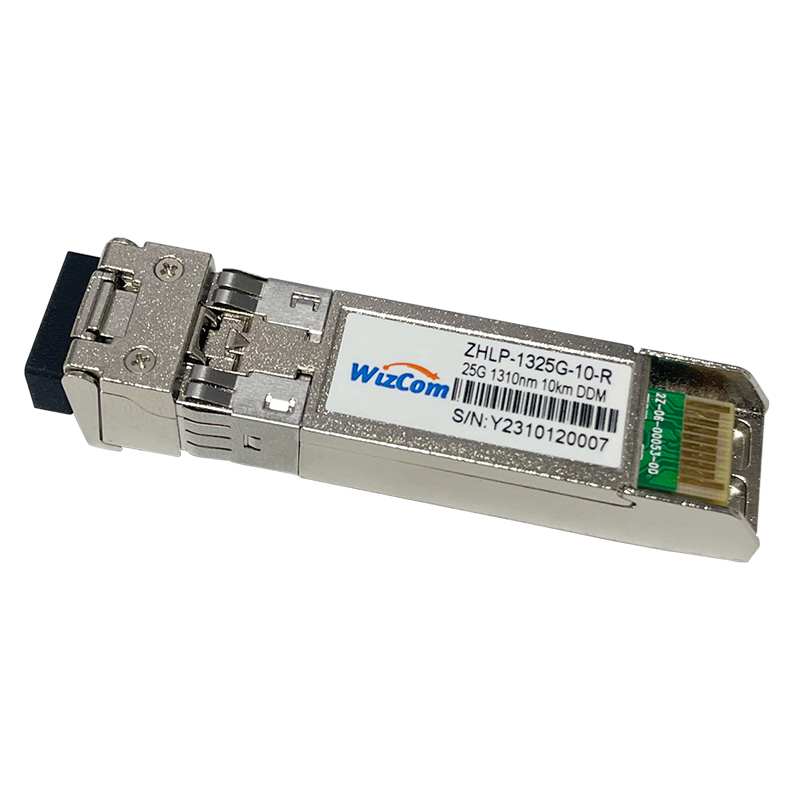


25Gbps 10km Duplex LC SFP28 Transceiver
description2
Specification parameter
Name |
25G single mode |
||
Model number |
ZHLP-1325G-10-R |
Brand |
Zhilian Hengtong |
Package type |
SFP28 |
Transmission rate |
25G |
Wave length |
1310nm |
Transmission distance |
10km |
Port |
LC |
Fiber type |
9/125µm SMF |
Laser type |
DFB |
Receiver type |
PIN |
Transmitted optical power |
-5~+2dBm |
Receiving sensitivity |
-11.4dbm |
Power |
<1.32w |
Receive overload |
2dBm |
Power dissipation |
|
Extinction ratio |
≥3DB |
CDR (Clock Data Recovery) |
support |
FEC function |
|
Commercial temperature |
0~70℃ |
Agreement |
INF-8431/SFF- 8472/IEEE802.3cc |
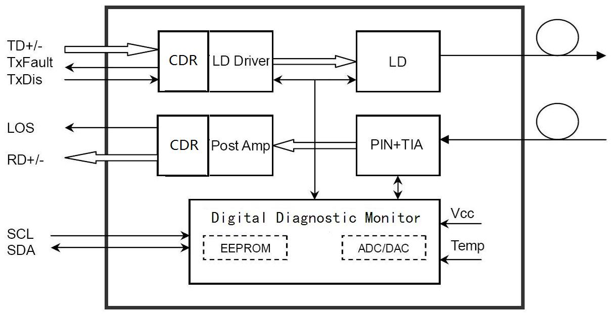
Module Block Diagram
Features
Applications
Standards
Recommended Operating Environment
Parameter |
Symbol |
Min. |
Typical |
Max. |
Unit |
|
Power Supply Voltage |
VCC |
3.13 |
3.3 |
3.46 |
V |
|
Power Supply Current |
ICC |
|
|
400 |
mA |
|
Operating Case Temperature |
Commercial |
TC |
-5 |
|
+70 |
°C |
Extended |
-20 |
|
+80 |
|||
Industrial |
-40 |
|
+85 |
|||
Data Rate |
|
|
25.78 |
|
Gbps |
|
Electrical Characteristics
Parameter |
Symbol |
Min. |
Typical |
Max. |
Unit |
Note |
Transmitter Section |
|
|||||
Input Differential Impedance |
Rin |
90 |
100 |
110 |
Ω |
|
Differential Data Input Swing |
Vin PP |
200 |
|
900 |
mV |
1 |
Transmit Disable Voltage |
VD |
Vcc – 1.3 |
|
Vcc |
V |
|
Transmit Enable Voltage |
VEN |
Vee |
|
Vee+ 0.8 |
V |
|
Receiver Section |
|
|||||
Differential Data Output Swing |
Vout PP |
400 |
|
900 |
mV |
|
LOS Fault |
Vlos fault |
Vcc – 0.5 |
|
Vcc_host |
V |
2 |
LOS Normal |
Vlos norm |
Vee |
|
Vee+0.5 |
V |
2 |
Optical Parameters
Parameter |
Symbol |
Min. |
Typical |
Max. |
Unit |
Note |
Transmitter Section | ||||||
Centre Wavelength |
λc |
1295 |
1310 |
1325 |
nm |
|
Spectral Width(-20dB) |
Δλ |
|
|
1 |
nm |
|
Side Mode Suppression Ratio |
SMSR |
30 |
|
|
dB |
|
Average Optical Power (avg.) |
Pout |
-5 |
|
+2.0 |
dBm |
1 |
Laser Off Power |
Poff |
- |
- |
-30 |
dBm |
|
Extinction Ratio |
ER |
3 |
- |
- |
dB |
2 |
Relative Intensity Noise |
RIN |
- |
- |
-130 |
dB/Hz |
|
|
Transmitter and Dispersion Penalty |
TDP |
|
- |
2.7 |
dB |
|
Optical Return Loss Tolerance |
|
- |
- |
26 |
dB |
|
Output Optical Eye |
Compliant with IEEE802.3cc eye masks when filtered |
2 |
||||
Receiver Section |
|
|||||
Receiver Center Wavelength |
λc |
1260 |
1310 |
1355 |
nm |
|
Receiver in Average Power |
|
-11.4 |
|
2 |
dBm |
|
Receiver sensitivity(OMA) |
Sen |
|
|
-12 |
dBm |
3 |
Los Assert |
LOSA |
-26 |
- |
- |
dBm |
|
Los Dessert |
LOSD |
- |
- |
-17 |
dBm |
|
Los Hysteresis |
LOSH |
0.5 |
- |
5 |
dB |
|
Overload |
Pin-max |
- |
- |
2 |
dBm |
3 |
Receiver Reflectance |
|
- |
- |
-26 |
dB |
|
Receiver Power (damage) |
|
- |
- |
3 |
dBm |
|
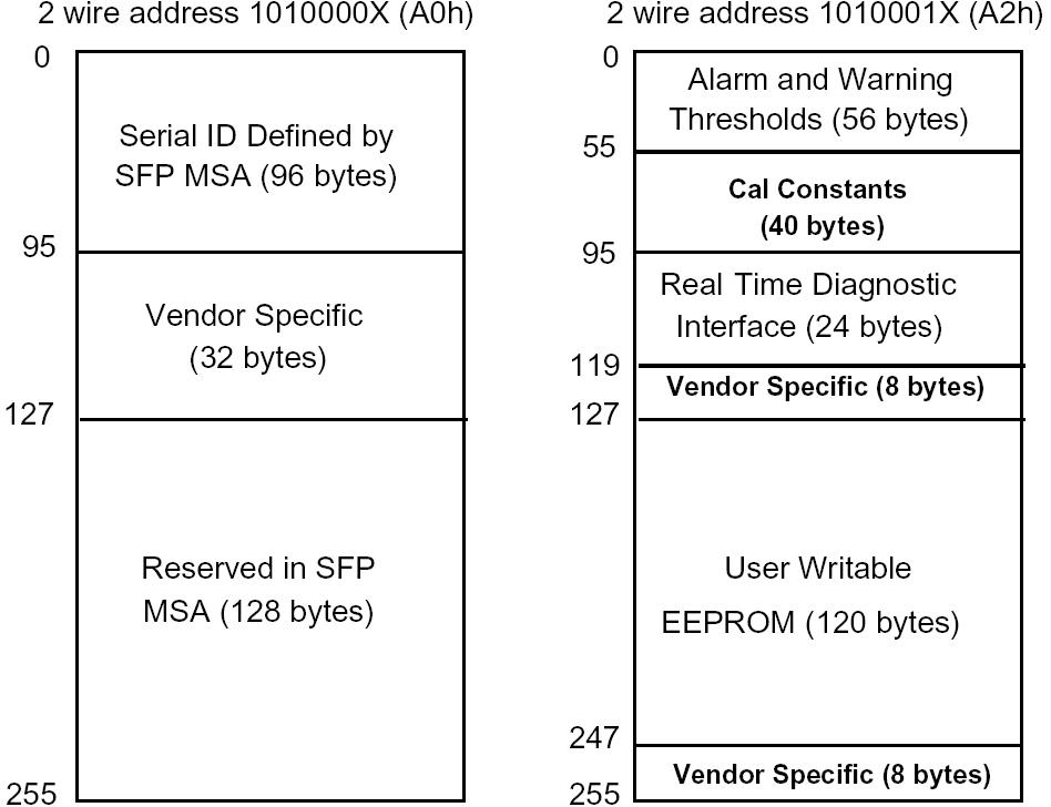
Digital Diagnostic Memory Map (Compliant with SFF-8472)
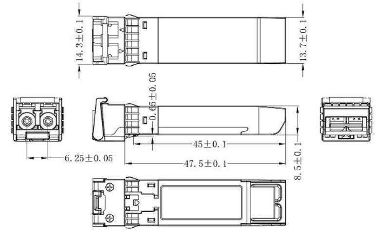
Mechanical Dimensions