Coaxial Cable
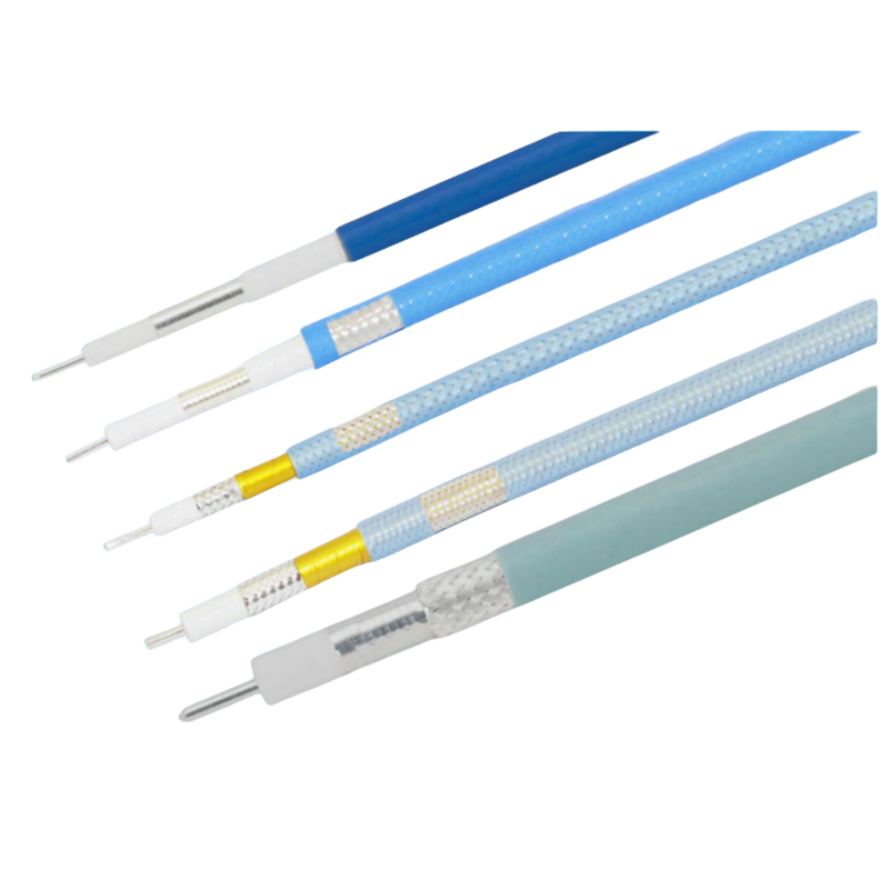
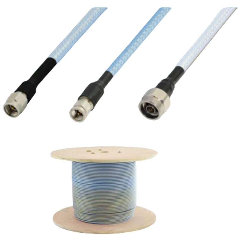
JB series low loss stable amplitude flexible coaxial cable
description2
Specification parameters
Cable type |
JB230 |
JB360 |
JB400 |
JB460 |
JB520 |
JB600 |
|
Structure & Material & Size |
mm |
mm |
mm |
mm |
mm |
mm |
|
Center conductor |
Silver-plated copper |
0.51 |
0.72 |
0.91 |
1.02 |
1.29 |
1.57 |
Dielectric medium |
Low density PTFE |
1.52 |
2.21 |
2.75 |
3.05 |
3.85 |
4.72 |
Outer conductor |
Silver plated copper tape |
1.72 |
2.4 |
2.95 |
3.32 |
4. 15 |
5. 18 |
interlayer |
PTFE/ Aluminum foil |
N/A |
2.8 |
3.07 |
3.45 |
4.28 |
5.3 |
External shield |
Silver plated copper wire |
2.04 |
3. 15 |
3.5 |
4.02 |
4.73 |
5.8 |
sheath |
FEP |
2.4 |
3.6 |
4 |
4.6 |
5.2 |
6.2 |
Main parameter index
Cable type |
JB230 |
JB360 |
JB400 |
JB460 |
JB520 |
JB600 |
Operating frequency |
67GHz |
40GHz |
26.5GHz |
26.5GHz |
26.5GHz |
18GHz |
Characteristic impedance |
50Ω |
50Ω |
50Ω |
50Ω |
50Ω |
50Ω |
Transmission rate |
74% |
74% |
76% |
76% |
76% |
76% |
Dielectric constant |
1.83 |
1.83 |
1.73 |
1.73 |
1.73 |
1.73 |
Time delay |
4.50nS/m |
4.50nS/m |
4.38nS/m |
4.38nS/m |
4.38nS/m |
4.38nS/m |
capacitance |
92.9 pF/m |
90.5 pF/m |
87.0 pF/m |
87.9 pF/m |
88 .0pF/m |
87.4 pF/m |
inductance |
0.22µH/m |
0.22µH/m |
0.22µH/m |
0.22µH/m |
0.22µH/m |
0.22µH/m |
Dielectric withstand voltage |
400(V , DC) |
600(V , DC) |
700(V , DC) |
800(V , DC) |
1000(V , DC) |
1300(V , DC) |
Shielding efficiency |
<-90dB |
<-90dB |
<-100dB |
<-100dB |
<-100dB |
<-100dB |
Static bending radius |
12mm |
18mm |
20mm |
23mm |
26mm |
31mm |
Dynamic bending radius |
24mm |
36mm |
40mm |
46mm |
52mm |
62mm |
weight |
16g/m |
33g/m |
45g/m |
50g/m |
50g/m |
90g/m |
Operating temperature |
-55 ~ 165℃ |
|||||
Product features
Applications
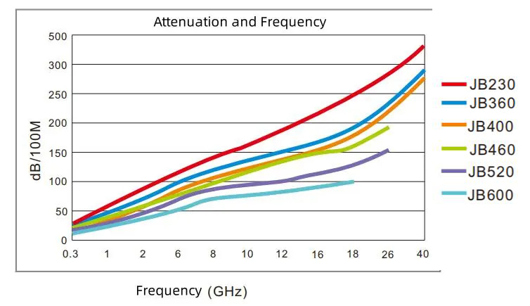
Attenuation and frequency variation plots
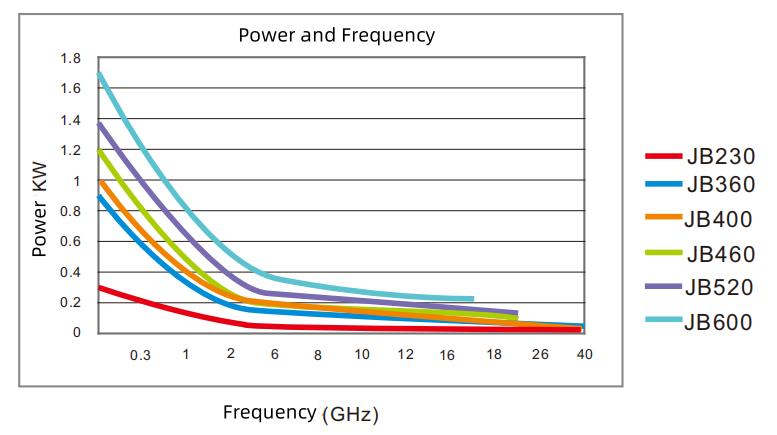
Average power and frequency variation graph
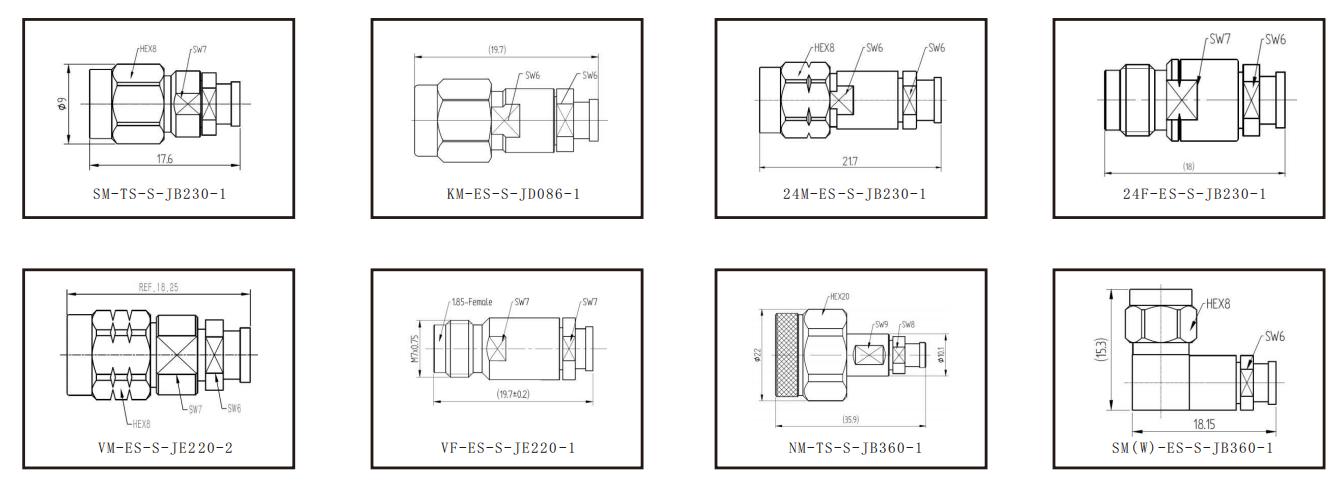
Partial adapter connector dimensions