
Company News

Wire bonding tool bonding wedge
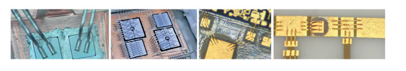
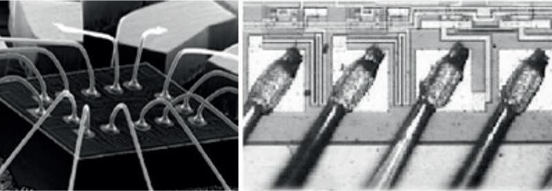
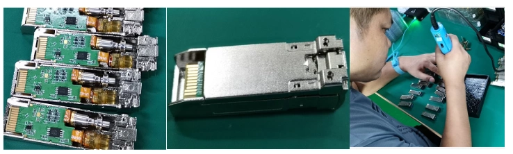
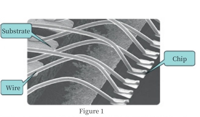
This article introduces the structure, materials, and selection ideas of commonly used bonding wedge for micro assembly wire bonding.The splitter, also known as the steel nozzle and the vertical needle, is an important component of wire bonding in the semiconductor packaging process, which generally includes cleaning, device chip sintering, wire bonding, sealing cap and other processes. Wire bonding is a technology to realize the electrical interconnection and information intercommunication between the chip and the substrate. The splinter is installed on the wire bonding machine. Under the action of external energy (ultrasonic, pressure, heat), through the plastic deformation of metal and the solid phase diffusion of atoms, the wire (gold wire, gold strip, aluminum wire, aluminum strip, copper wire, copper strip) and the bonding pad are formed. To achieve the interconnection between the chip and the circuit,as shown in Figure 1.
1. Bonding wedge structure
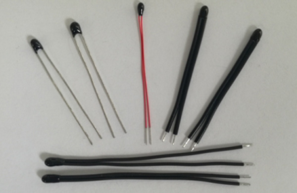
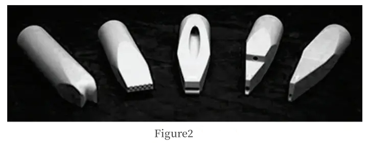
The main body of the splitting tool is usually cylindrical, and the shape of the cutter head is wedge-shaped. The back of the cutter has a hole for penetrating the bonding lead, and the hole aperture is related to the wire diameter of the lead used. The end face of the cutter head has a variety of structures according to the needs of use, and the end face of the cutter head determines the size and shape of the solder joint. When in use, the lead wire runs through the opening hole of the splitter and forms a 30° ~ 60° Angle between the lead wire and the horizontal plane of the bonding area. When the splitter drops to the bonding area, the splitter will press the lead wire on the bonding area to form a shovel or horseshoe solder joint. Some Bonding wedge are shown in Figure 2.
2. Bonding wedge material
During the working process of bonding, the bonding wires passing through the bongding wedege generate pressure and friction between the cleaver head and the solder pad metal. Therefore, materials with high hardness and toughness are usually used to make cleavers. Combining the requirements of chopping and bonding methods, it is required that the chopping material has high density, high bending strength, and can process a smooth surface. Common cutting materials include tungsten carbide (hard alloy), titanium carbide, and ceramics.
Tungsten carbide has strong resistance to damage and was widely used in the production of cutting tools in the early days. However, the machining of tungsten carbide is relatively difficult, and it is not easy to obtain a dense and pore free processing surface. Tungsten carbide has a high thermal conductivity. In order to avoid the heat on the solder pad being carried away by the cutting edge during the bonding process, the tungsten carbide cutting edge must be heated during the bonding process.
The material density of titanium carbide is lower than that of tungsten carbide, and it is more flexible than tungsten carbide. When using the same ultrasonic transducer and the same blade structure, the amplitude of the blade generated by the ultrasonic wave transmitted to the titanium carbide blade is 20% greater than that of the tungsten carbide blade.
In recent years, ceramics have been widely used in the production of cutting tools due to their excellent characteristics of smoothness, density, no pores, and stable chemical properties. The end face and hole processing of ceramic cleavers are better than those of tungsten carbide. In addition, the thermal conductivity of ceramic cleaves is low, and the cleave itself can be left unheated.
3. Bonding wedge selection
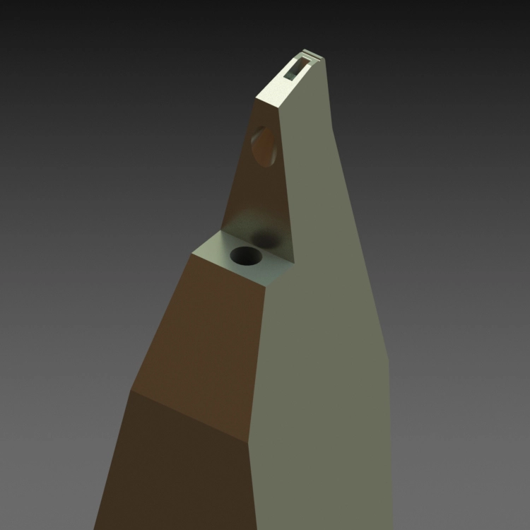
The selection determines the bonding quality of the lead wire. Factors such as bonding pad size, bonding pad spacing, welding depth, lead diameter and hardness, welding speed and accuracy should be considered comprehensively. Wedge splits are typically 1/16inch (1.58mm) in diameter and are divided into solid and hollow splits. Most wedge splits feed the wire into the bottom of the cutter at a 30°, 45°, or 60° feed Angle. Hollow splitters are selected for deep cavity products, and the Wire is vertically passed through the hollow wedge splitter, as shown in Figure 3. Solid cleavers are often selected for mass production because of their fast Bond rate and high solder joint consistency. Hollow splits are chosen for their ability to Bond deep cavity products, and the difference in bonding with solid splits is shown in Figure 3.
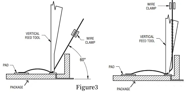
As can be seen from the figure 3, when bonding a deep cavity or there is a side wall, the Wire of the solid split knife is easy to touch the side wall, causing a hidden Bond. Hollow split knife can avoid this problem. However, compared with solid split knife, hollow split knife also has some shortcomings, such as low bonding rate, difficult to control the consistency of solder joint, and difficult to control the consistency of tail wire.
The tip structure of the Bonding wedge is shown in Figure 4.
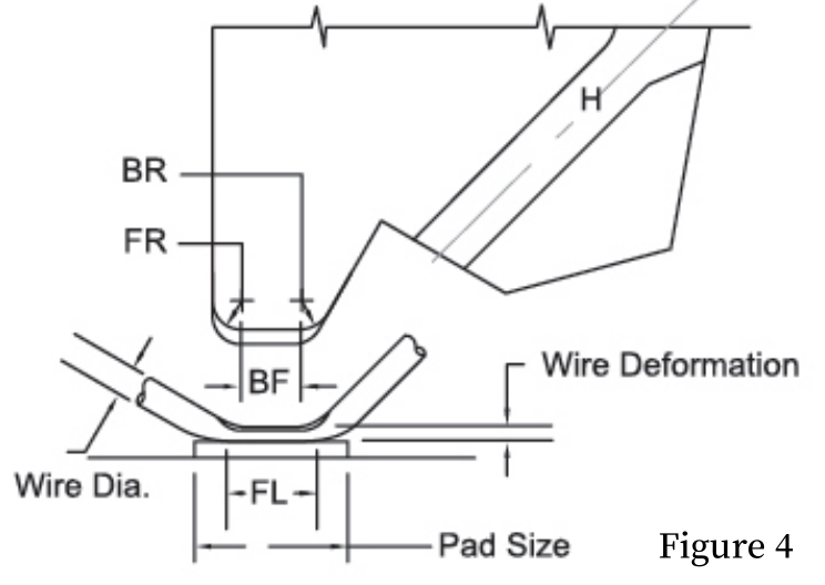
Hole Diameter(H):The aperture determines whether the bonding line can pass through the cutter smoothly. If the inner aperture is too large, the bonding point will be offset or LOOP offset, and even the solder joint deformation is abnormal. The inner aperture is too small, the bonding line and the inner wall of the splitter friction, resulting in wear, reduce the bonding quality. Since the bonding wire has a wire feeding Angle, the gap between the hole of the bonding wire and the split knife must generally be greater than 10μm to ensure that there is no friction or resistance during the wire feeding process.
Front Radius (FR):FR basically does not affect the first bond, mainly provides the LOOP process, for the second bond transition, to facilitate line arc forming. Too small FR selection will increase the crack or cracking of the second welding root. Generally, the size selection of FR is the same as or slightly larger than the wire diameter; For gold wire, FR can be selected to be less than the wire diameter.
Back Radius (BR):BR is mainly used to transition the first bond during the LOOP process, facilitating the arc forming of the first bond line. Secondly, it facilitates wire breakage. The selection of BR helps to maintain consistency in the formation of tail wires during the wire breakage process, which is beneficial for tail wire control and avoids short circuits caused by long tail wires, as well as poor deformation of a solder joint caused by short tail wires. Generally speaking, gold wire uses a smaller BR to help cut the wire clean. If BR is selected too small, it is easy to cause cracks or fractures at the root of a solder joint; Excessive selection may result in incomplete wire breakage in the welding process. The size selection of general BR is the same as the wire diameter; For gold wire, BR can choose to be smaller than the wire diameter.
Bond Flat(BF):The selection of BF depends on the Wire Diameter and Pad Size. According to GJB548C, the length of the wedge weld should be between 1.5 and 6 times that of the Wire Diameter, as too short keys can easily affect the bonding strength or the bond may not be secure. Therefore, it generally needs to be 1.5 times larger than the Wire Diameter, and the length should not exceed Pad Size or 6 times longer than the Wire Diameter.
Bond Length(BL):BL is mainly composed of FR, BF and BR as shown in Figure 4. Therefore, when the Pad Size is too small, we must pay attention to whether the Size of FR, BF and BR of the splitting knife is within the Pad Size to avoid exceeding the Pad solder joint. Generally BL=BF+1/3FR+1/3BR.
4.Summarize
Bonding wedge is an important tool for microassembly lead bonding. In the civil field, lead bonding is mainly used in chip, memory, flash memory, sensor, consumer electronics, automotive electronics, power devices and other industries. In the military field, lead bonding is mainly used in RF chips, filters, missile seeker, weapons and equipment, electronic information countermeasures system, spaceborne phased array radar T/R components, military electronics, aerospace, aviation and communications industries. In this paper, the material, structure and selection idea of common Bonding wedge are introduced, which is helpful to help users choose the most suitable wedge splits, so as to obtain good welding quality and reduce cost.